Parallax Shift
* I’m putting an asterisk up here to mean “It’s more complicated than that.” Feel free to refer to this note wherever you see another asterisk below.
Mind Games
Making a texture appear to be on a different plane from the surface of an object is as simple as applying an offset to the texture’s position which varies with the position or rotation of the surface. This creates a parallax effect in your mind.
You can achieve this in a shader by adjusting the texture’s UV coordinates based on the view angle. (This kind of real-time UV manipulation is called “perturbation” which suggests that it bothers them, but in my experience they don’t mind.)
Perturbing UVs is easy enough, but how do you know in which direction to perturb? Sadly, this requires math.
When moving a background-image in a div with CSS, much of this math is either automatic or unnecessary, because the view angle is constant relative to the scene and the transformations are always relative to their parent. But in a shader on an object in a 3D scene, none of this is taken for granted.
There Are Four Spaces
To get the math right, you have to get your conceptual spaces in order. In this case, there are four* we need to consider: view space, world space, object space, and tangent space. Don’t freak out! The names are weird, but the concepts are simple. Each conceptual “space” is just a frame of reference with its own “right”, “up,” and “in,” otherwise known as X, Y, and Z axes.
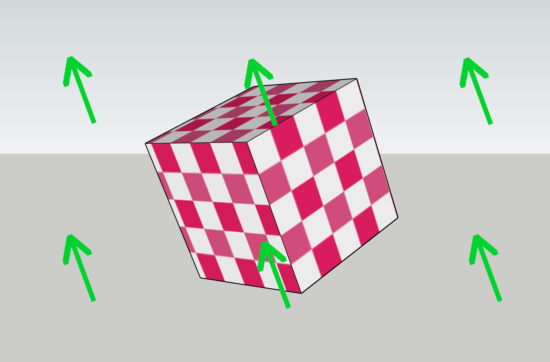
An example: Which way is up in the images below, according to the view? This one’s easy, because the view is through a 3D camera, and cameras have a built-in “up”. No matter which way the camera points or how it’s rotated, “up” is the same direction relative to the camera. View space is the conceptual space (aka a coordinate system) in which this is true.
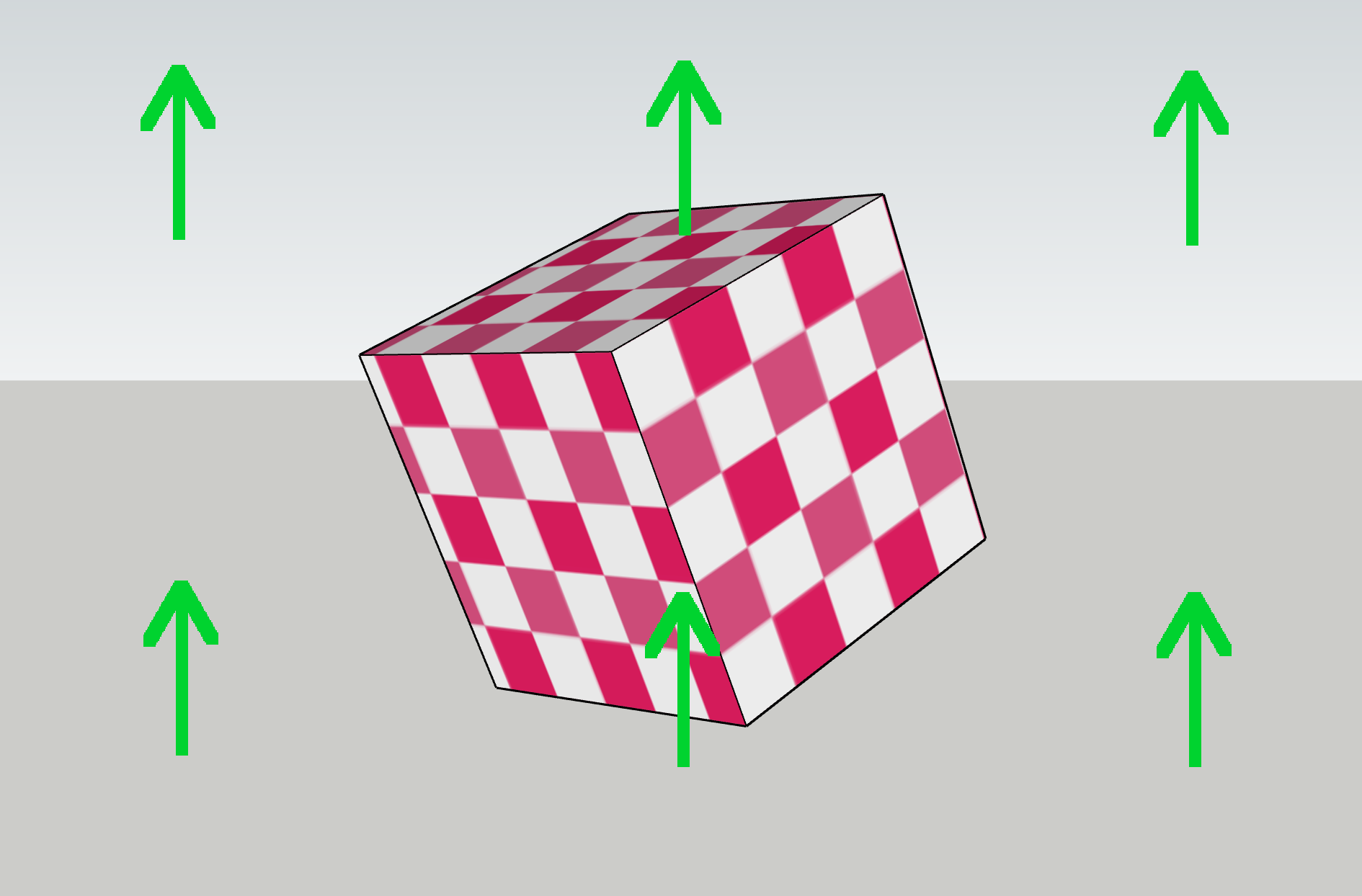
Now, which way is up in world space, as seen through the view? This is slightly trickier, because of perspective. In the center of the view, world-space “up” matches view-space “up” (assuming the camera isn’t tilted). But off to one side, “up” can be angled relative to the view, due to perspective.
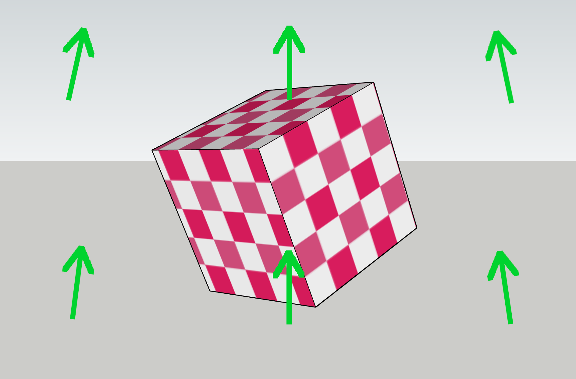
Now: which way is up, relative to the object? This one’s easy again, as objects are defined with an internal “up,” so object space just follows the orientation of the object. However, the actual orientation of the arrows on your screen is also affected by world space and view space, as the object is situated in both.
Now the tricky one: which way is up, relative to the surface of the object?
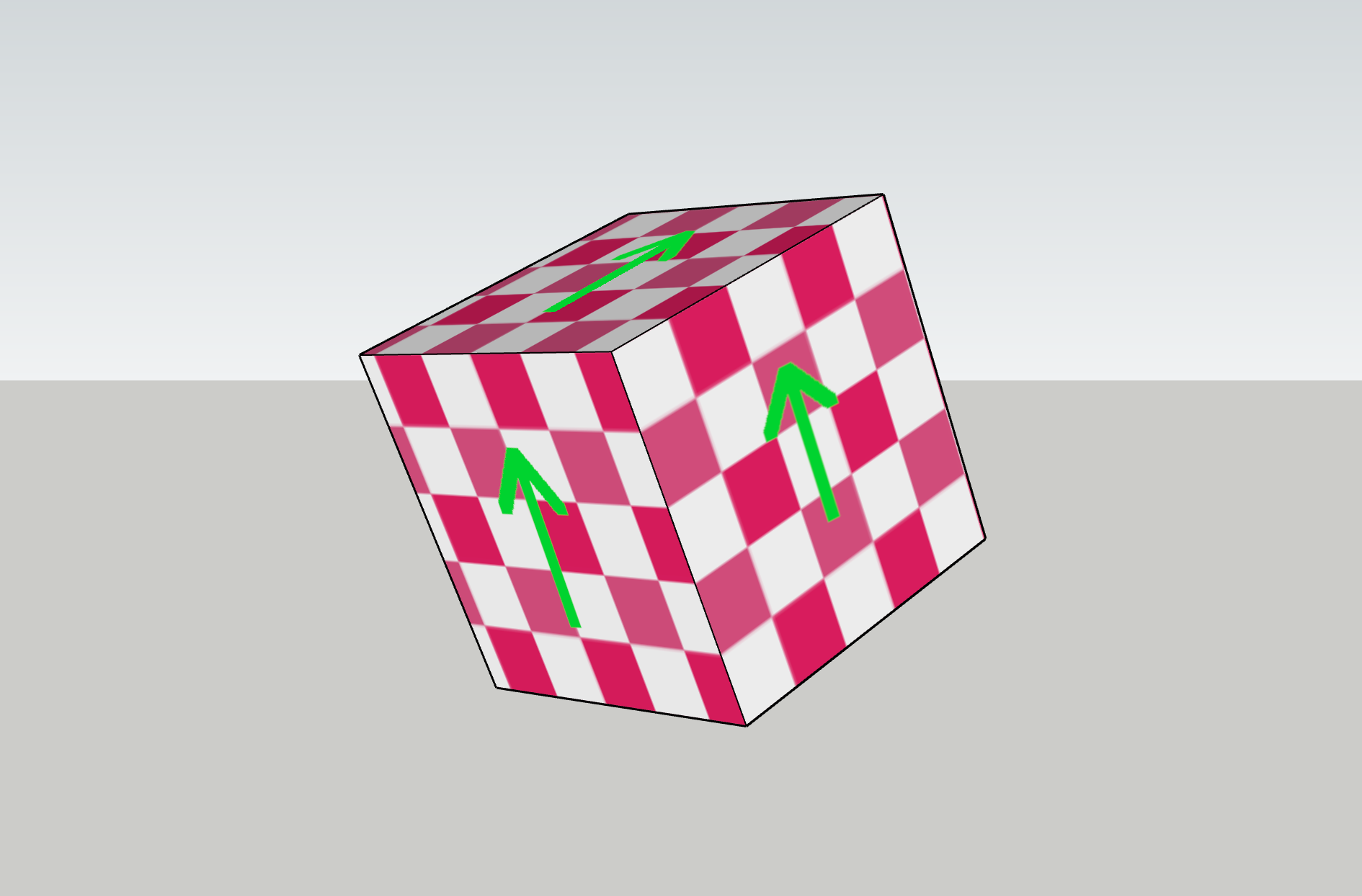
Any way could be up! It’s arbitrary. What’s more, it varies across the object and is in fact defined separately for each vertex, and can vary across a face. It can even be changed at runtime, by rotating the vertices independently of the object! This is probably the trickiest conceptual leap to make, and is the main reason the math in this shader is tricky.
The abstract space in which all those arrows point the same direction is known as tangent space and is defined locally for each point on an object’s surface. It’s closely related to the realm of UV mapping, which relates textures to faces, but unlike UVs, tangent space is not a typical component of shaders. So it must be derived from the UVs and other available spatial information, including the view angle and the surface normal.
Finally, texture lookups can be performed to manipulate the pixels in the input texture. In your standard shader-free environment, this all happens semi-automagically* in a chained process that looks like this:
texture → UV map → tangent space → object space → world space → view space → output pixel
Even in the average shader, most of these steps are not necessary to specify explicitly, because default 3D pipelines assume all of this. However, our shader relies on selective manipulation of the UV coordinates for each point on the surface of an object. In a way, it’s replacing the typical function of the “UV map” step above. That means it needs to take all four spaces plus the UV coordinates into account when performing its calculations, and it needs to do it backwards.
Finding the Perpendicular
The primary function of the shader, speaking technically, is to wiggle some pixels around. But which way, and how far? Let’s look at a simple case to understand the parameters of this problem.
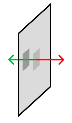
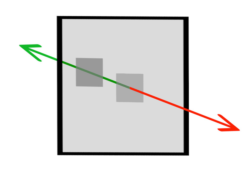
The card below has been rotated at an angle in 3D. On it are two grey squares. The red arrow is the surface’s “out” direction, also known as the normal, and the green arrow is the “in” direction. The grey square on the left looks further “in” from the surface of card, as though it had been pushed along the green direction.
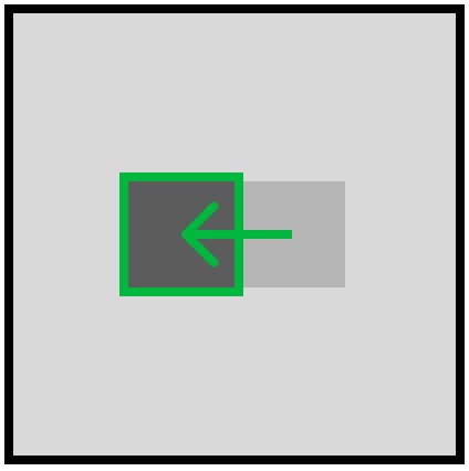
Now let’s turn the card to face us, so we’re seeing it in texture space.
From the texture’s point of view, the “in” vector is slightly up and to the left. However, if any of the pieces of our puzzle change – say, the card rotates, or our view changes – that vector will change too. The shader calculates this displacement vector, through another chain that mirrors the one above, but in reverse:
view orientation → world orientation → object orientation → tangent space orientation → displacement vector
Tunnel Vision
Now for the real kicker. We want to push pixels to different “depths” based on their brightness. This seems like it should be a relatively minor adjustment: you simply add a factor into the calculation based on the brightness of the pixel, right?
There’s a wrinkle in this plan, which has to do with the way a fragment shader works, which is by applying the exact same code to all the pixels individually, all at once*. It can’t differentiate between pixels – it only knows “the pixel.” This means an OpenGL fragment shader can’t write to arbitrary pixel locations! However, it can read pixels from a texture at any location. So to “push” a pixel, you must structure the shader so that when it’s drawing the pixel in the destination location, it finds and “pulls” the pixel from the correct origin location instead.
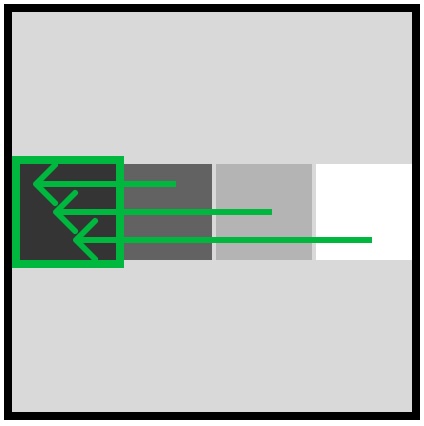
An example: say we know we want to push the lighter square below to the location of the darker square. We would have to write our shader so that when it’s drawing the pixel at the dark square’s location, it performs a lookup at the light square’s location, and uses that color instead. Then, when drawing the pixel at the light square’s location, it should draw the background color, or nothing.
Okay, easy enough. But there’s another wrinkle! (This is a very wrinkly problem.) Because we want to push pixels based on brightness, the pixel which should be in the current location might be one of a number of brightnesses. So the origin pixel could come from… lots of places! All we know for sure is the direction. But there might be lots of pixels in that direction which could be moved – which one should we choose?
Multiple Choice
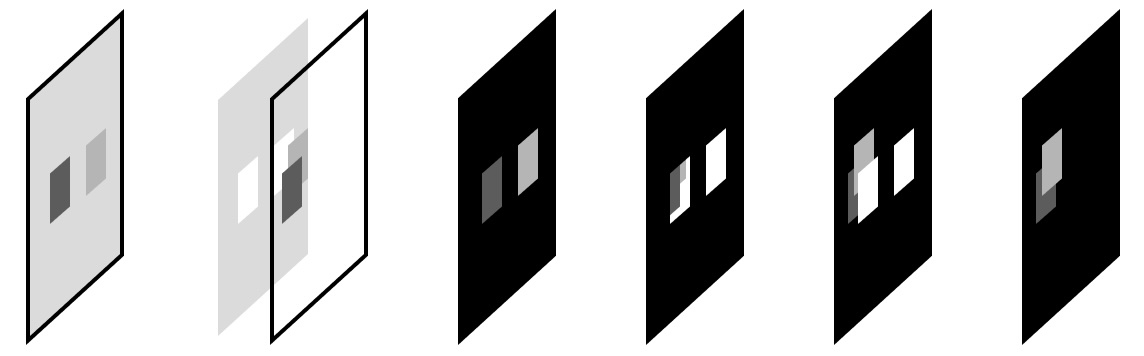
The last challenge here has to do with occlusion, which in a standard parallax shader is a fundamental component. These shaders iterate over the pixels using a kind of painter’s algorithm, preferentially drawing “closer” pixels. In this way perspective is maintained, closer pixels occlude further pixels, and the surface remains solid. However, for a transparent crystal with internal and possibly-occluding details, we want this to be handled differently.
To solve this problem, the crystal shader looks for all possible matches along the perturbation vector, and takes the brightest. This is equivalent to the lightest blending mode in WebGL – other blend modes are possible, but this is the method I used here. (This was the last CSS demo in the previous post.) This handles both the occlusion problem and the question of which pixel to use in the case of multiple matches, mentioned above.
Below is a diagram illustrating these concepts, which I will not explain.
Shader Time
First, creds: This shader is based on a techbrood demo, which was in turn based on work from Igor Dykhta and the venerable Morten S. Mikkelsen. My thanks to all involved.
We’ll start with the vertex shader, which simply positions the vertices and sets up some information which will be needed by the fragment shader. Most of this is fairly standard boilerplate for shaders which perform normal mapping, which is objectively the coolest and most useful computer graphics technique. I once literally bumped into the guy who invented it.
// define varyings, special shader variables which allow information to be passed to the fragment shader
varying vec3 vNormal;
varying vec2 vUv;
varying vec3 vViewPosition;

void main() {
  // set uv varying
  vUv = uv;

  vec4 mvPosition = modelViewMatrix * vec4( position, 1.0 );
  // set viewPosition varying – this is the position in view space
  vViewPosition = mvPosition.xyz;

  // calculate normal in view space and set normal varying
  vNormal = normalize(normalMatrix * normal);

  // set vertex positions
  gl_Position = projectionMatrix * modelViewMatrix * vec4(position, 1.0);
}
The vViewPosition and vNormal calculations convert the position and normal vectors into view space, which is crucial for this effect – we must know the relationship of these vectors to the view in order to move the textures in the right direction and by the right amount.
The Fragment Shader
The fragment shader performs a number of steps, all in service of “pushing” pixels in the texture some distance behind the face they’re painted on. Bear in mind that these steps are performed for each pixel in the output, every frame, up to 60 frames per second. GPUs are amazing!
Let’s look at an outline first, then we’ll dig into each step:
- Initialize everything
- Calculate the offset direction
- Step through the texture with an offset
- Sample the texture in the offset direction and set output color
Step 1: Initialize Everything
// pull in uniforms from the cpu
uniform float _steps; // number of displacement layers
uniform float _height; // maximum displacement distance
uniform float _scale; // texture scale
uniform float _opacity; // texture opacity
uniform sampler2D _texture; // the texture itself

// pull in varyings from the vertex shader
varying vec2 vUv;
varying vec3 vNormal;
varying vec3 vViewPosition;
Step 2: Calculate the offset direction
This is the gnarly one. First, the main() function initializes a couple of variables, then calls perturbUv(). This function returns the maximum texture offset vector for the current pixel – in other words, given the _height uniform, the maximum distance into the face to push the current pixel.
void main() {

  float lum;
  vec3 color = vec3(0.);

  // perform the actual parallax mapping calculation. it takes the view position and the surface normal as arguments.
  vec2 maximumOffset = perturbUv( vViewPosition, normalize( vNormal ));
Now let’s step into perturbUv():
vec2 perturbUv( vec3 viewPosition, vec3 surfNormal ) {

  // partial derivatives of the texture coordinates (vUv) with respect to the screen-space x and y coordinates.
  vec2 texDx = dFdx( vUv );
  vec2 texDy = dFdy( vUv );
A word of appreciation for the dFdx and dFdy functions, which are the workhorses of advanced shaders, and are crucial to this one in particular. These functions calculate the partial derivatives of something, one piece at a time. In this case, we’re interested in knowing, essentially, the slope of the UVs, because we don’t have direct access to the geometry, and want to understand the relationship between the UVs and screenspace.
The UVs could be described as a 2D function that can be analyzed in any direction, with a different slope depending on which direction you’re facing. However, a partial derivative of a function with multiple factors only concerns itself with one factor at a time and ignores the rest, and this happens to be ideal in situations where your inputs are 2D grids, like bitmaps or things which map to bitmaps, like UV maps.
We use dFdx and dFdy again with the surface coordinates, which give us more information about where and how the current pixel to be drawn is oriented in space.
  // partial derivatives of surfPosition with respect to screen-space x and y coordinates. they represent the change in the world-space position along the x and y axes in screen space.
  vec3 vSigmaX = dFdx( surfPosition );
  vec3 vSigmaY = dFdy( surfPosition );
Once we have these pieces, we use them to construct the tangent space, through the use of a transformation function helpfully called the TBN matrix. This is constructed by taking the cross product of those last two partial derivatives with the surface normal, which produces vectors perpendicular to both:
  // vR1 and vR2: tangent vectors used to build the TBN (tangent, bitangent, normal) matrix, which is used to transform vectors from tangent space to view space.
  vec3 vR1 = cross( vSigmaY, surfNormal );
  vec3 vR2 = cross( surfNormal, vSigmaX );
  // fDet is the determinant of the TBN matrix. It essentially ensures that the two cross products are scaled proportionally to the surface normal.
  float fDet = dot( vSigmaX, vR1 );
Confusingly, there’s no actual matrix constructed here, but we do get what is essentially three perpendicular vectors in space, which implies a matrix. I don’t fully understand everything you can do with a TBN matrix, but I do know why it’s important – faces don’t, by themselves, have an orientation. However, by combining all the things we know about the face’s surface normal and the UV orientation, we can construct something which functions like an orientation, which could be considered something like “face space”. This is the crucial piece of this puzzle – you have to have this imaginary space in order to know how and where to do the parallax mapping trick.
If you want more on the TBN matrix, the diagrams on this page do a good job of explaining it.
Anyway. The point is, you can use those three pieces to construct a TBN matrix. And if we had a TBN matrix, you could pull these pieces out again to do projection math. But since we have those three pieces, we can skip right past the matrix step and use them directly, to give us a vector which points “in”:
  // vProjVscr: a 2D vector that contains the projected view vector onto the tangent plane of the surface.
  vec2 vProjVscr = ( 1.0 / fDet ) * vec2( dot( vR1, viewPosition ), dot( vR2, viewPosition ) );
This step projects the view vector onto the surface, which tells us the relative angle between the view direction and the surface relative to the components of that vector. This gives us:
  // vProjVtex: a 3D vector in texture space that represents the direction of UV perturbation.
  vec3 vProjVtex;
  vProjVtex.xy = texDx * vProjVscr.x + texDy * vProjVscr.y;
  vProjVtex.z = dot( surfNormal, viewPosition );
Our vector! The one in texture space that we want! The green one we drew on the face, from the perspective of the texture!
  // _height is the maximum distance to perform the perturbation
  vec2 texCoordOffset = _height * vProjVtex.xy / vProjVtex.z;

  // return the offset uv
  return texCoordOffset;
Then we scale it by the _height setting and return it, and that’s the hard part over with.
Step 3: Step through the texture with an offset
Back in main(), we set up a loop based on the number of distinctions we want to make in the grayscale image, starting with the brightest possible value and stepping down to nothing. Theoretically, with an 8-bit black and white image, the loop could usefully have a maximum of 256 steps, assigning slightly different displacement values to each possible luminance value. For my purposes this was unnecessary overhead.
Conversely, with too few steps, the displacement is obviously quantized, which might be fine in some situations but I wanted to ensure an apparent semi-random distribution of features throughout the object. I found that using about 8 steps seemed to work well.
  // loop starting at the maximum value and stepping down by 1 each time
  for (float i = _steps + 1.; i >= 0.; i--) {
    float percent = (1. / _steps) * i;
    float next = (1. / _steps) * (i + 1.);

    // apply the offset to the UVs in steps, ending with the maximum offset
    vec2 newUv = vUv - maximumOffset * percent;
Note that in the last line, the offset is subtracted – this is what “slows down” the apparent motion of the displaced pixels, the same as in the examples from the last post.
Step 4: Sample the texture in the offset direction and set output color
The second half of the loop samples the target pixel, and saves the first one which matches the current range, setting it as the output. (If one thinks of the view direction as a “ray” and the looping steps as “marching” one might whimsically describe this process as “ray marching.”)
    // get the brightness of the pixel, in this case by simply taking the r channel's value. this assumes a grayscale texture.
    lum = texture2D( _texture, newUv  * _scale ).r; //
    // if the value of the sampled pixel falls within the current step percentage range, use it and stop. this chooses the brightest of the available values.
    if (lum >= percent && lum < next) {
      color = vec3(lum);
      break; // exit the loop
    }
  }

  // set the output fragment color
  gl_FragColor = vec4(color, _opacity); // sets rgb color plus alpha
Using this input texture…

…and these uniforms:
    _height: 1,
    _steps: 8,
    _scale: 4
The result is below! Adjust the uniform values to see their effect on the output:
View Source
This project is open-source. The relevant repos are here:
https://github.com/meetar/FS-reverse-parallax-plain/
And the full shaders are here:
https://github.com/meetar/FS-reverse-parallax-plain/blob/main/public/parallax.frag https://github.com/meetar/FS-reverse-parallax-plain/blob/main/public/parallax.vert
And a demo of this technique in a more complex shader setup is here:
https://meetar.github.io/reverse-parallax-shader/ code
I hope you found this post interesting! I wrote it to get a better understanding of what my shader was doing, so I pulled it apart and wrote until I did; and now so do you.*